

Moment Coefficient From Pressure Distribution
Aerodynamic Pitching Moment
Center of Force per unit area (CP)
The aerodynamic interaction of a fly with an airflow determines a distribution of varying local pressures and tangential stresses on the external surface. The surface exposed to the airflow is also called the wet surface of the fly. The same concept applies to all remaining parts of an aircraft, such as the external shape of the fuselage also as the wet surfaces of tailplanes.
The local pressures and tangential stresses, provided they are multiplied by the surface area $\mathrm{d}\mathcal{A}$ of the elemental wet surface, represent a system of practical forces. In full general, these forces are not-coplanar and not-parallel yet they can be resolved into an equivalent single forcefulness represented by the resultant, applied along a well adamant axis. The aerodynamic resultant $\boldsymbol{F}$ is a representative force which has the same concrete effect on a given trunk, in our case a wing or the entire aircraft, equally the grouping of forces it replaces. In aerodynamics this conceptual process is known every bit reduction of the overall aerodynamic action of the airflow on the aeroplane to the resultant aerodynamic force, practical to centre of pressure. Actually, the resultant can be applied to whatever given point of its line of action.
When airfoils are considered, the aerodynamic resultant is a strength per unit bridge $\boldsymbol{f}$ practical on a point on the chord, i.e. the center of force per unit area of airfoils is located on the chord. This is illustrated by the next figure. The vectors $\boldsymbol{n}$ are the local unit vectors normal to the airfoil and pressure difference vectors $(p-p_\infty)\boldsymbol{n}$ represent the local normal strains exerted on the airfoil external shape by the flow. These vectors, multiplied past the small areas $\mathrm{d}\mathcal{A} = \mathrm{d}s\cdot 1\,\mathrm{m}$ (where $\mathrm{d}s$ is the chemical element of curvilinear abscissa running forth the airfoil and $ane\,\mathrm{k}$ is the unit spanwise length) are forces distributed on the external surface of the airfoil. A symilar organisation of vector exists and is represented by the vectors $\tau_\mathrm{west}\boldsymbol{t}$, where $\tau_\mathrm{w}$ are the local viscous tangential stresses and $\boldsymbol{t}$ are the local unit vectors tangent to the airfoil. The ensemble of all these force vectors applied on the airfoil contour give rise to the the resultant $\boldsymbol{f}$ shown below.
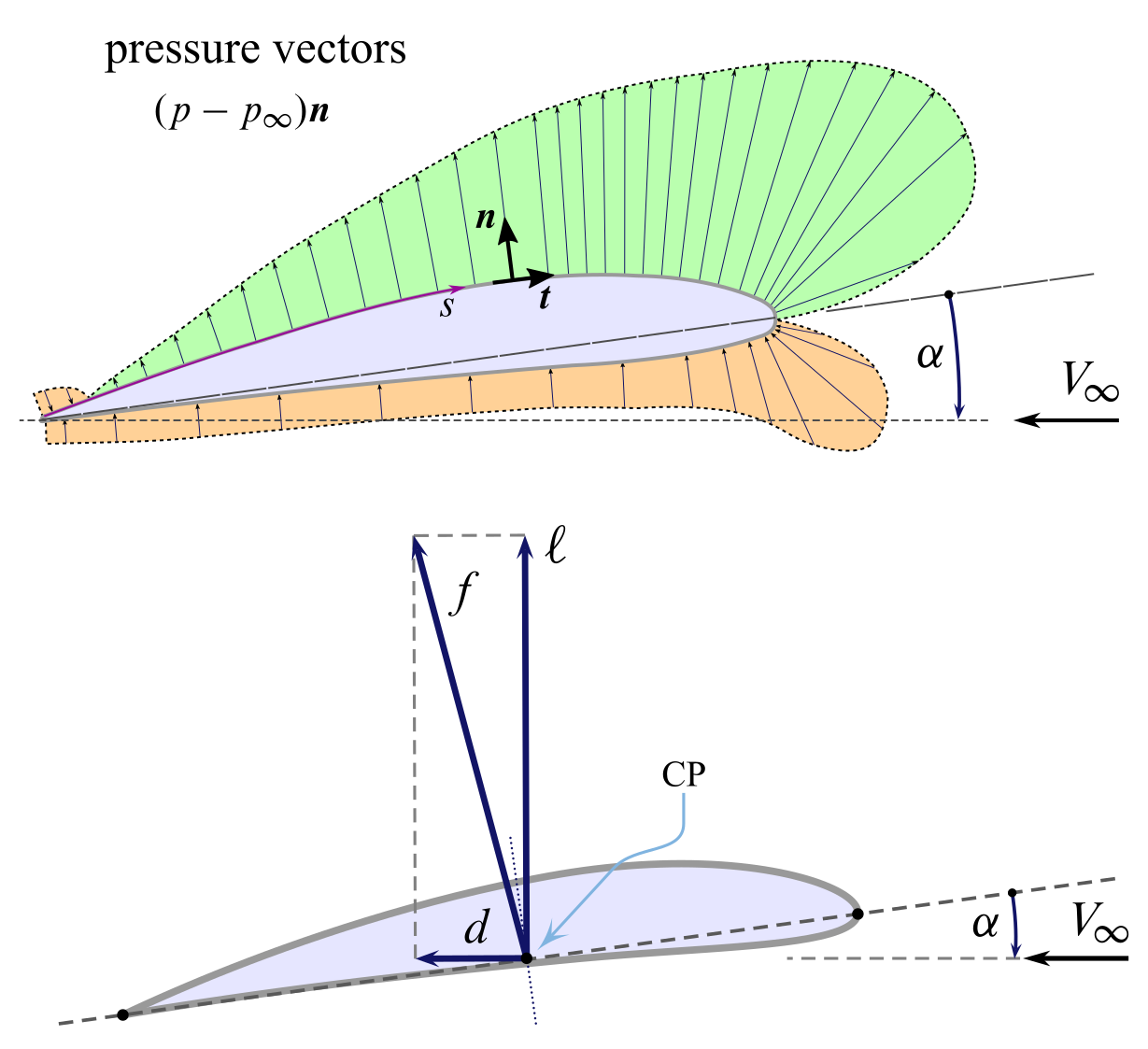
The system of all local external forces on the airfoil, due to the airflow of asymptotic speed $V_\infty$ at an angle of attack $\alpha$, is equivalent to the resultant $\boldsymbol{f}$, which is reduced to the center of pressure $\mathrm{CP}$. Therefore, to the point $\mathrm{CP}$ are applied both the lift per unit span $\ell$ and the drag per unit span $d$.
The same is done for finite wings for which the middle of pressure is taken on the root chord, i.e. the resultant $\boldsymbol{F}_\mathrm{W}$ acts in the airplane of symmetry.
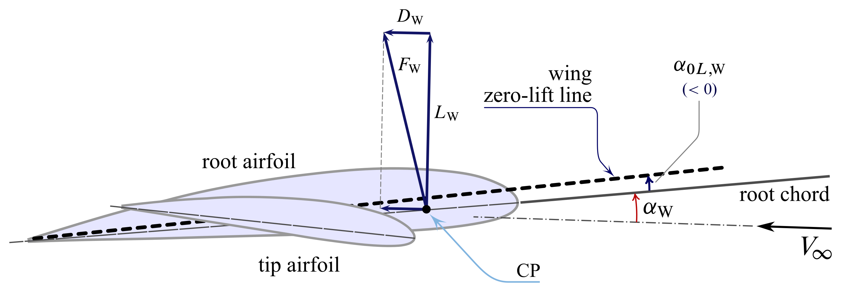
Due to the high values of aerodinamic efficiencies of airfoils and wings, often one can neglect the elevate component in the above constructions, i.e. $d\approx 0$ and $D_\mathrm{W}\approx 0$.
Aerodynamic Middle
The effigy below represents an airfoil at a given angle of attack $\alpha$. The pressure and tangential stress distributions on the airfoils are reduced, if one neglects the elevate, to the sole lift $\ell$ applied to the heart of pressure. Information technology is known from aerodynamics that, for a fixed airspeed $V_\infty$, an increasing angle of assail determines an increase of $\ell$ and a move of the point $\mathrm{CP}$ forth the chord towards the leading border. This forwards shift takes place until $\alpha$ reaches the stall angle of set on $\alpha_\mathrm{stall}$ of the airfoil then, for a further increment of $\alpha$, the center of force per unit area starts moving backwards.
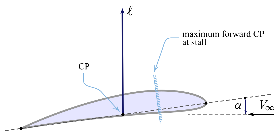
On the other terminate, for decreasing $\alpha$'s the center of pressure shifts backwards while $\ell$ decreases. The point $\mathrm{CP}$ tends to move infinitely downstream as $\blastoff$ approaches the angle $\alpha_{0\ell}$ and $\ell$ tends to naught.
It should be noted that, beingness the arrangement of external aerodynamic forces equivalent to the force $\ell$ applied in $\mathrm{CP}$, the moment $m_P$ per unit span of aerodynamic forces with respect to a given pole $P$ is equal to the moment of the reduced system with respect to $P$. The effigy below explains this concept.
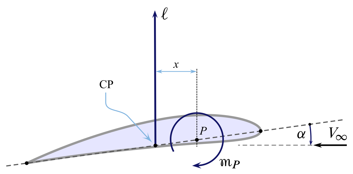
If $x$ is the arm of $\mathrm{CP}$ to $P$ the aerodynamic moment is
\begin{equation} m_P = - \ell \, x \label{eq:Airfoil:Moment:P} \terminate{equation}
For $\ell$ and $ten$ positive as shown, the resulting pitch-downwards couple is negative past definition. If the angle of assail changes, both $\ell$ and $10$ will alter and so will do $m_P$.
The variability of the aerodynamic reduction bespeak $\mathrm{CP}$ is an unfavourable circumstance when the aerodynamic behaviour of wings and tailplanes take to be evaluated to appraise the pitching equilibrium or pitching dynamics of a consummate aircraft. Fortunately, the experimental evidence confirms the existence of a particular focal point along the chord of airfoils that exhibits a unique property: the pitching moment of the lift with respect to this point is invariant with the angle of attack. This item pole is called aerodynamic center (ac) and for slender airfoils it is located approximately at a distance of $c/four$ from the leading border.
A qualitative plot of the airfoil moment coefficient with respect to the quarter chord point \begin{equation} C_{m_{c/iv}} = \frac{m_{c/4}}{\frac{1}{two}\rho V^two c^2} \label{eq:Airfoil:Moment:c4} \end{equation}
is reported in the next figure.
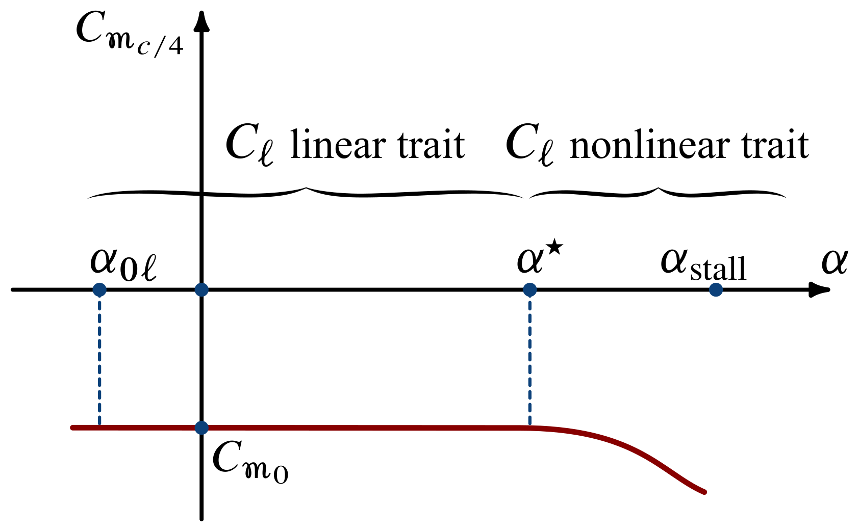
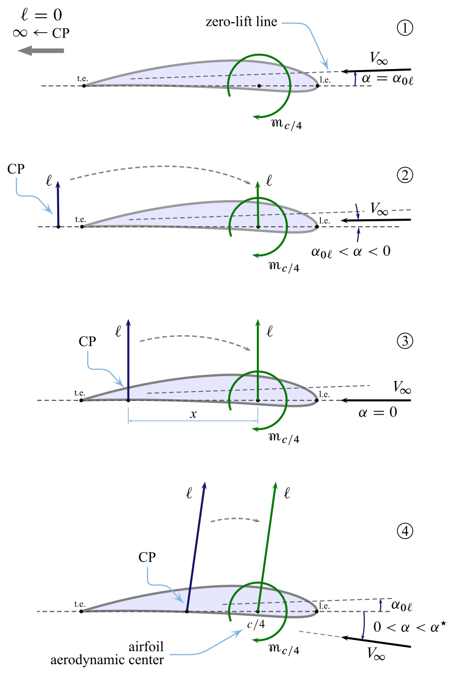
The non-variability of $C_{m_{c/4}}$ of airfoils with the angle of assault is well explained by the post-obit figure, where four conditions of increasing $\blastoff$ are considered.
- In the get-go condition, at an angle $\alpha = \alpha_{0\ell}$, the $\mathrm{CP}$ is located ideally at a distance $x\rightarrow\infty$ from the pole, nonetheless the lift $\ell = 0$. The aerodinamic pressures and tangential stresses at the contour surface have a zippo resultant but are not nix, and their resultant pitching moment with respect to the pole is not-null either being equal to $C_{m_0}$. In such a case, when the resultant is nil, the aerodynamics of the airfoil is reduced to a sole costless couple.
- In the subsequent weather condition, from 3 to iv, the resultant $\ell$ is not goose egg but the advancing $\mathrm{CP}$ and the increasing lift are such that the product $-\ell\,x$ remains equal to $C_{m_0}$.
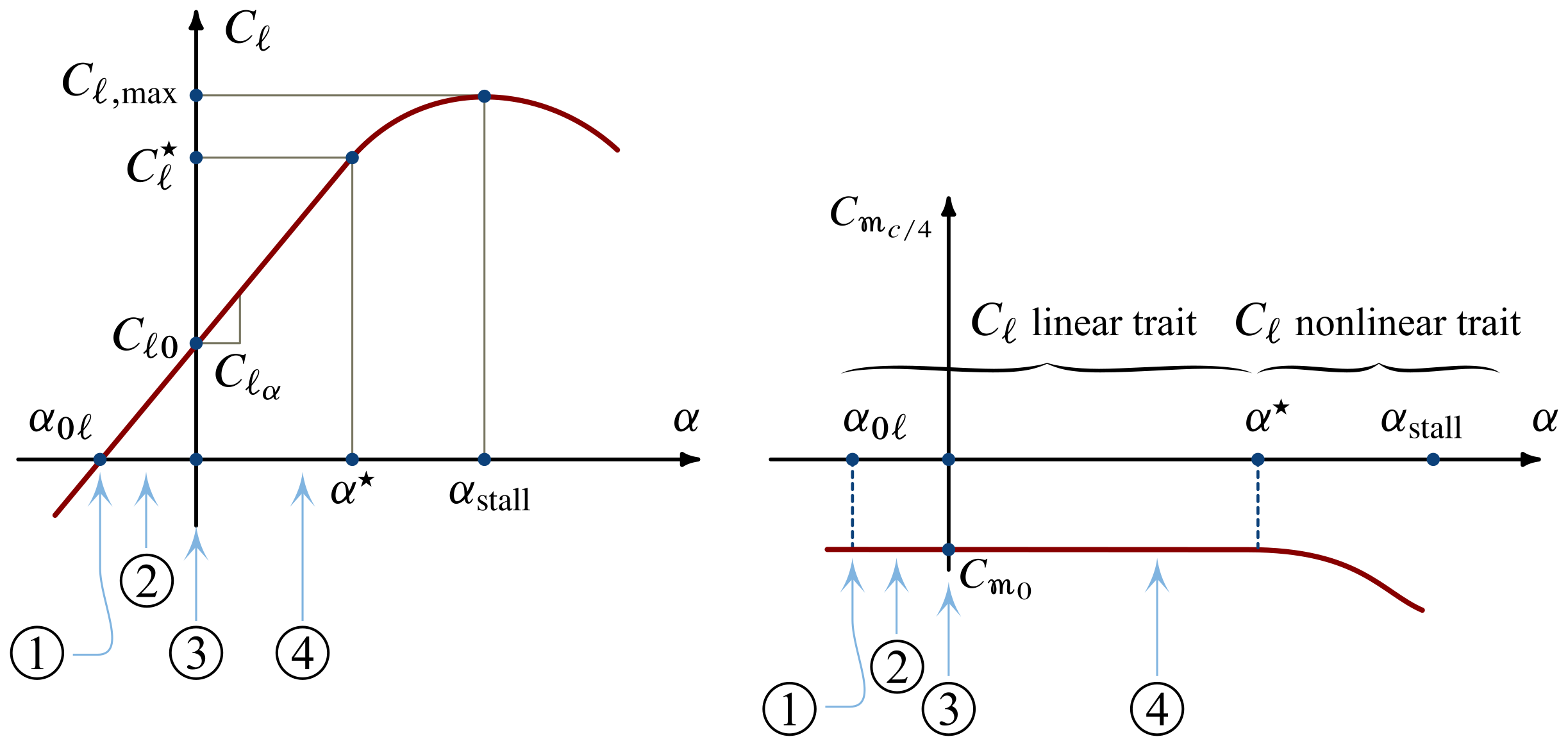
The four conditions considered in the previous figure are reported below on the curves of $C_\ell$ and $C_{m_{c/4}}$ as functions of $\blastoff$. It must exist noted that the existence of a focal point is justifiable strictly for those angles of attack within the $C_\ell$ linearity range.
Finite wings are three-dimensional lifting surfaces that have the aforementioned characterisics of airfoils. Therefore, an aerodynamic center also exists for wings. As shown in the side by side top view of a wing, in the three-dimensional instance the focal indicate 'air-conditioning' is in the symmetry aeroplane, somewhere on the root chord or, co-ordinate to the situation, on the projection of the hateful aerodynamic chord.
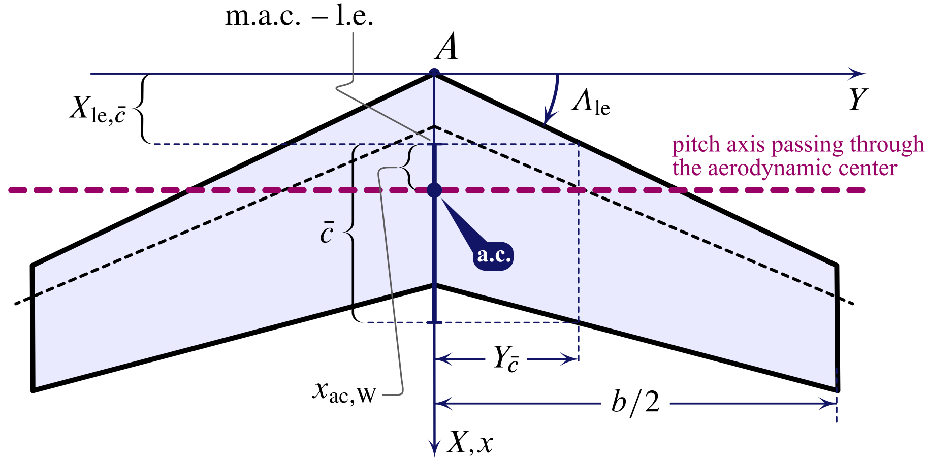
For wings one tin can speak of focal axis, i.e. a pitch axis passing through the aerodynamic heart and such that the pitching coefficient
This is confirmed by the next plot for all angles of attack $\alpha_{0L,\mathrm{W}} \le \alpha_\mathrm{W} \le \alpha_\mathrm{West}^\star$.
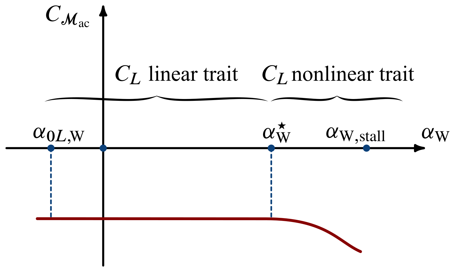
The existence of the aerodynamic center of wings, i.e. a pitch focal centrality, is such a favourable circumstance: as the angle of assault changes, the aerodynamic outcome of the airflow over the lifting surface can be reduced to the lift $L_\mathrm{W}$ applied to the fixed point 'ac' and to a abiding moment $\mathcal{M}_\mathrm{ac}$ about the same pole.
A very important practical outcome of this circumstance is illustrated by the side by side figure. When 1 needs to evaluate the aircraft baricentric pitching moment due to the aerodynamics of the wing, it tin be but calculated by multiplying $L_\mathrm{W}$ times the arm $a$ and and so adding the couple $\mathcal{1000}_\mathrm{air conditioning,W}$.
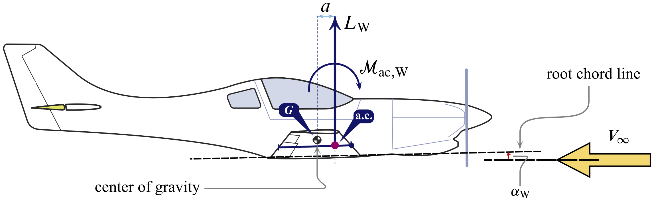
Therefore, the pitching moment of the fly nigh the aircraft center of gravity $Chiliad$ is:
The respective pitching moment coefficient
can be calculated considering that
and substituting into the expression (\ref{eq:Wing:Moment:M}), to obtain the equation:
The above expression can be rearranged as the following linear formula in $\alpha_\mathrm{B}$:
where the 2 constants are defined as:
The to a higher place 2 constants are known by the designers, for a given flight condition, once the geometry of the wing and the center of gravity position are known.
Effect of the fuselage
When a wing-fuselage configuration is considered, also called wing-body by engineers, the concept of aerodynamic center (or focal pitch centrality) remains. Fuselages of conventional airplanes develop nearly no lift but are subject area to a pitching moment due to airflow. By adding the fuselage to the wing it can be shown that their combination nevertheless exhibits an aerodynamic middle.
The figure below shows a side view of an airliner.
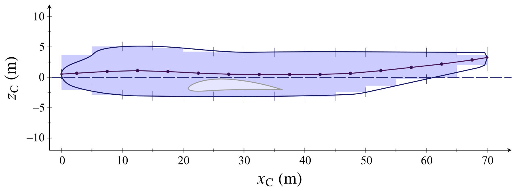
This particular shape, when immersed in an air stream at an angle of attack $\alpha_\mathrm{B}$, generates a pitching moment $\mathcal{M}_{\mathrm{B}}$. A typical behaviour of this kind of stretched, cylinder-like shapes is shown in the next plot representing the pitching moment coefficient of the fuselage
as a office of the angle of attack.
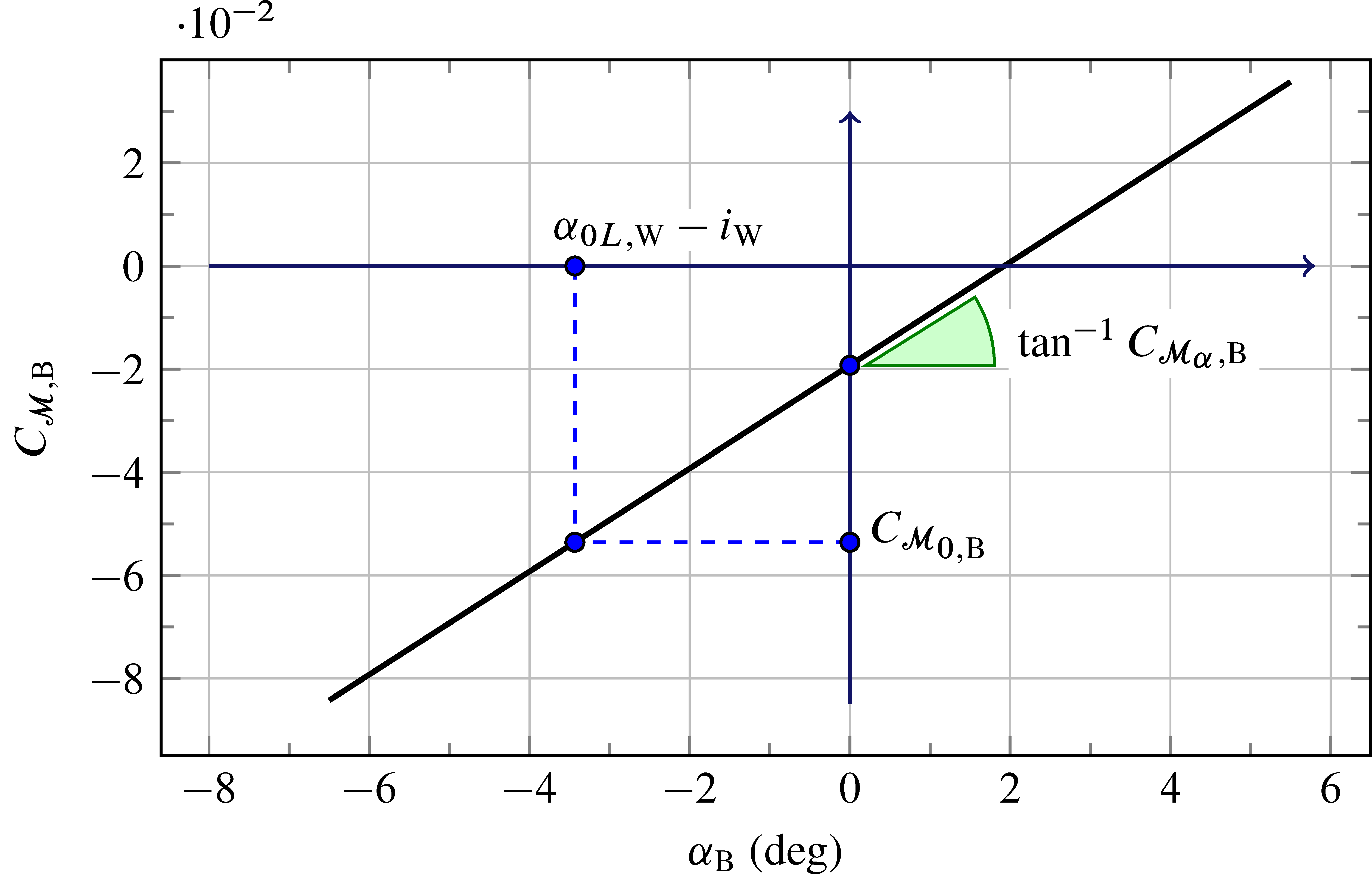
The positive slope of the above linear dependency from $\alpha_\mathrm{B}$ is un unfavourable circumstance for the longitudinal stability of airplanes.
The shipping longitudinal stability is discussed in more detail in the section on pitch stability and control .
The important practical outcome of the in a higher place give-and-take is illustrated by the next figure. When one considers the fly-fuselage (WB) combination, typically the aerodynamic center shifts forwards with respect to the original position determined for the isolated wing (W). Therefore, in the elevation view reported beneath the wing-trunk aerodynamic heart is located at the distance $x_{\mathrm{air-conditioning,WB}}$ from the leading border of the fly aerodynamic chord $\bar{c}$, which is less than the distance $x_{\mathrm{ac,Westward}}$ of the focal axis of the isolated wing.
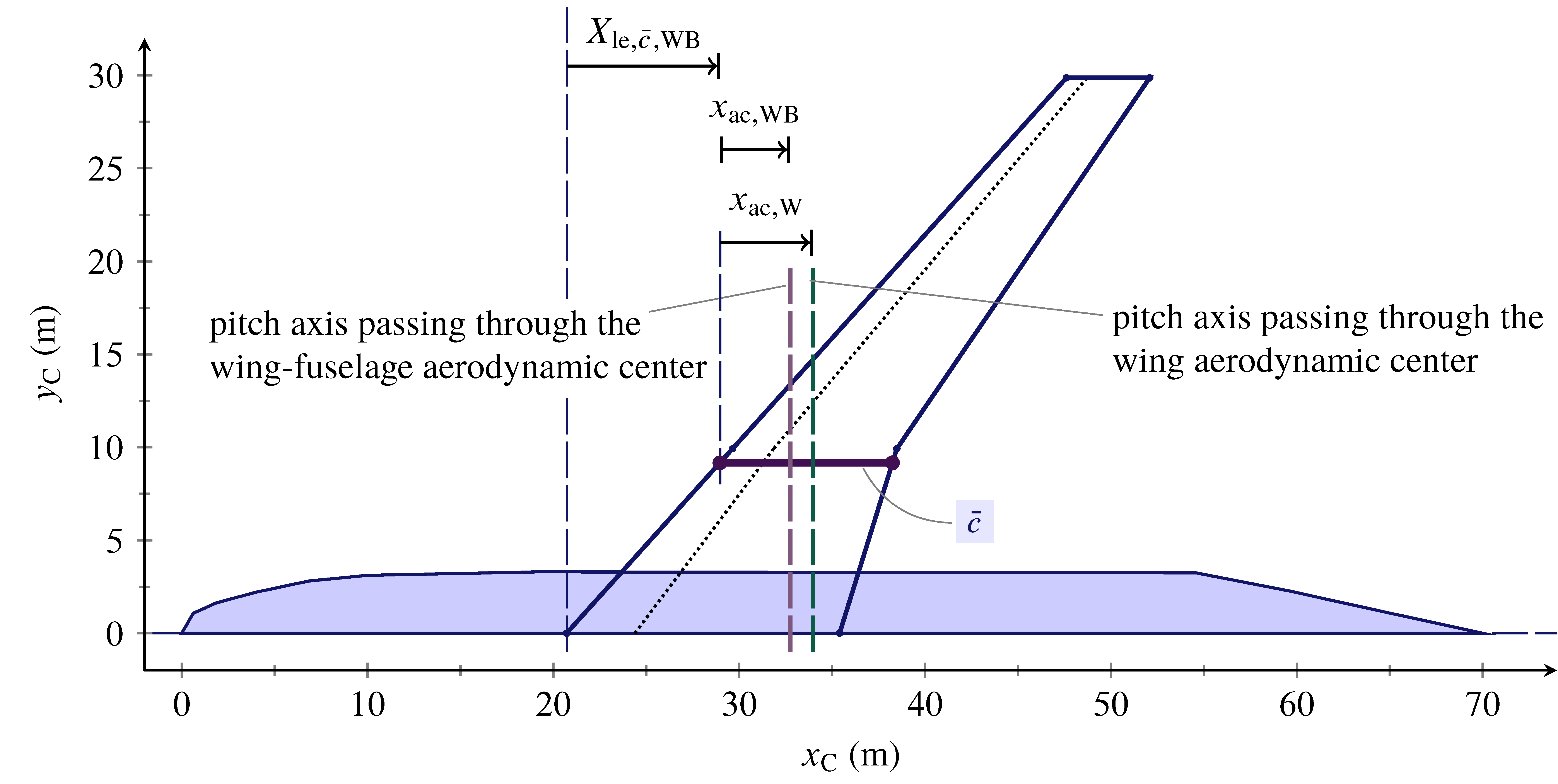
In other terms, the presence of the fuselage does not add together a significant lifting capacity to the wing but moves the aerodynamic center towards the nose.

Moment Coefficient From Pressure Distribution,
Source: https://agodemar.github.io/FlightMechanics4Pilots/mypages/pitching-moment/
Posted by: baskettpeaced1970.blogspot.com
0 Response to "Moment Coefficient From Pressure Distribution"
Post a Comment